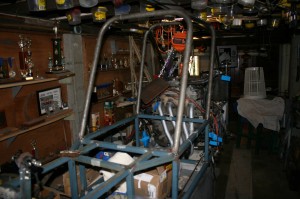
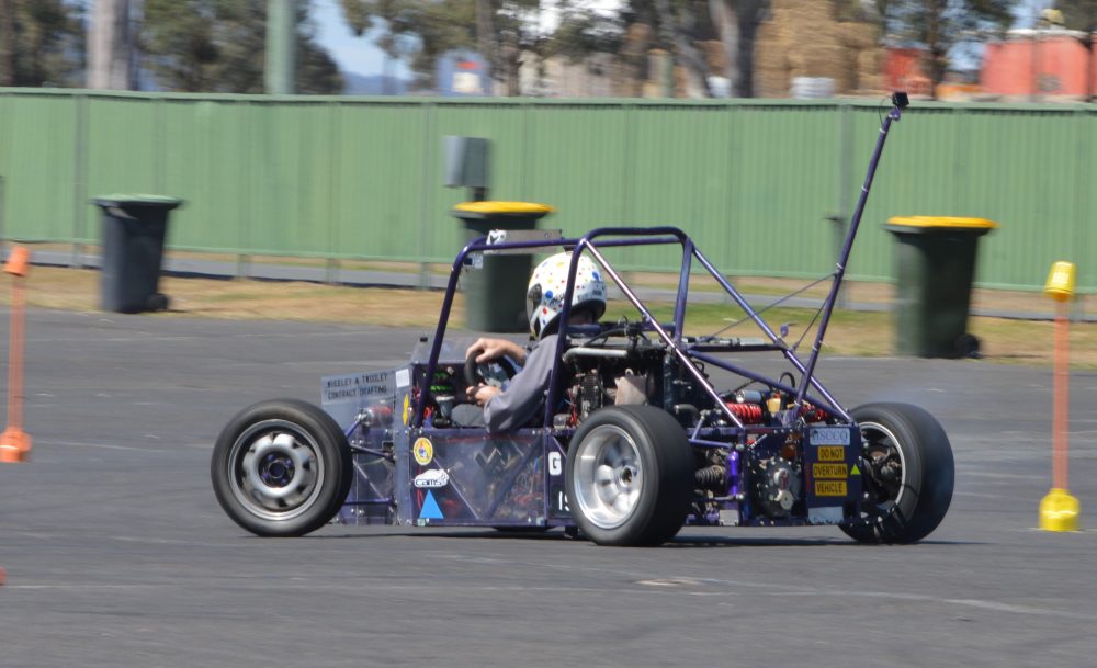
Construction of the eighth motorkhana special has actually started, and this blog will be upgraded every week or so to show the progress. The name for the car has been chosen, and it is Geococcyx Velox. The Lesser Roadrunner, located mainly in Mexico, and is smaller and browner than its American Cousin Geococcyx Californianus. I did not want it to be called “an american areshole”. It is powered by a Yamaha FJR1300 motor, which is supposed to have 145 HP (instead of the current car’s 75), and three times the torque rating of the existing car. This motor was purchased from Melbourne, and arrived on 29th December, 2009. It took some time to sort it out, and get the motor out of the alloy frame for the bike. The radiator had been damaged and was broken around one of the outlets, and replacements are very expensive. I bought a second hand radiator from a dirt bike for $10, and found that it was completely clogged with dried mud and dirt. A quick blast with the Karcher cleared it all, and looks brand new.
Because the new motor is shaft drive, a right angle gearbox to transmit the shaft drive into the input shaft of the VW Golf Mk 1 gearbox had to be designed, and the internal gears purchased from TEA Transmissions in Tiaro. The box was fabricated from a piece of 100 x 3 SHS, with a removable top section. Bearing housings were fabricated from 40 NB pipe, and bolt to the walls of the SHS. 20 mm sealed ball bearings do the rotation of the shafts, and a clutch spigot welded to the output shaft. This was completed on 21-11-2011.
The actual chassis frame was started on 11-1-2012, and is made from 25 x 1.6 SHS, with 540 mm inside the rear frame members, (top & bottom), and 300 mm between them vertically. Brackets were fitted to this to mount the VW Golf Mk 1 gearbox, and brackets to mount the motor in the chassis. The front engine mounts are bolted to the motor, and the horizontal SHS member sits on the top chassis rails where it bolts on. This is to make the engine removal and refitment easy.
Steel plate mounts for the right angle drive box were fabricated, and the area above it where the bell housing is situated was infilled with light gauge metal. The driveshaft from the engine to the right angle box was manufactured with a double plate joint in the centre.
The fuel injection had come off the block of the motor during transport, and it was replaced using a special home made allen wrench. The standard bike airbox is huge, and would have gone almost to the rear of the chassis, so the nose was cut off a VW Golf Mk 1 airbox to allow 4 pipes of 38 mm diameter to fit into it, and a light gauge sheet metal plate fabricated to suit. 4 pieces of this tube fit between the rubber pipes on the injector plate to replicate the long injector tubes, and the Golf airbox fitted up to it. The inlet tube for this airbox was long enough to foul with the rear dampers, so it was cut short.
The exhaust system was next, and the original primary pipes were badly crushed when the bike was crashed, so only the first bend and about 120 mm length was useable. Mandrel bends of 90 degrees were bought from the muffler shop, with a 4 into 1 collector, and a 2 inch bend included. A jig to replicate the position of the exhaust ports and all the motor mounts was fabricated, and the exhaust system welded up with difficulty because the primary pipes are very thin and made from some unusual material, and they were very difficult to weld without blowing holes in them. The exhausts were fitted on 15-11-2012.
The cleaned radiator with its fan was mounted on 22-11-2012, and the original alloy transfer pipes made for the FJR radiator were modified to suit the smaller radiator. The coolant reservoir went on a few days later.
The front part of the chassis was tacked together on 26-11-2012, and joined with the rear part of the chassis. Diagonal members to strengthen this area were tacked in. The right angle drive gearbox had dedicated chassis mounts fabricated, and light gauge sheet meatal covers the rest of the bell housing.
The 1-5 gear linkages were manufactured using M6 rod end bearings and transfer shafts going to the lever in the cockpit, which is topped by a hand carved silky oak wooden ball of 40 millimetres diameter. Then the two alloy pedals were folded up from the old alloy side panels from special No 6 (Gonzales).
A driveshaft for a FJR1300 arrived from USA on 10-12-2012, and it was cut short and butt welded to the short stub axle on the right angle drive gearbox. Next day the two roll bars were cut to length and angle, and tack welded to the chassis. The 1.6 mm Zincanneal floor pan, firewall and seat sides were fitted, and upholstery and padding fitted to them. The seat cushion and seat back were fitted with home sewn covers in red vinyl.
A three litre fuel tank for a kart was purchased, and mounting brackets built to hold it in place. The fuel pump was positioned below it, and the fuel lines to the injectors sorted out and plumbed. The mounts for the rear suspension units were fabricated, and the intake oval tube of the VW Golf air cleaned cut short to clear.
All the rear suspension mounts were tacked to the chassis on 19-12-2012, and the clutch lines and master cylinder re-positioned. A new aluminium clutch lever was hand built from part of the original FJR alloy chassis, but I made it opposite hand from what it was supposed to be. 4 hours work down the drain. A new one was made from 10 mm alloy plate. The operation rods to the pedal were fitted with M6 rod ends.
A zig-zag mounting bar for the front suspension mounts was fabricated and tack welded into the front chassis. The dashboard brace member was tacked in place on 2-1-2013, and the steering shaft made from some old 3/4″ OD tubing, bolted into the universal joint on the steering rack. A pressed plummer bearing was fitted to the dashboard brace to support the steering column, and a suitable bolt found to use as the steering wheel boss.
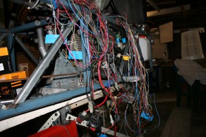
Next day saw some of the unwanted wiring removed from the loom. Things like lights, windscreen wiring and the like were identified. This will be a long job. The brake master cylinders were positioned on a small frame, and extensions made from the brake balance bar to the cylinders. Designs were produced for two different turning brake arrangements. One similar to the existing car with individual levers on each side of the car working different rear wheel brakes; and a single lever arrangement where the lever is mounted on the right hand side of the cockpit, and it is pushed to operate the right hand side brake, and pulled to operate the left hand side brake. The latter one was manufactured on 5-1-2013, with an intricate brass ferrule that allows the lever to move back and forth but only operate one cylinder at a time.
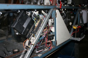
After weeks of work, the wiring nightmare that was the original harness has been redone, with all the main components installed flush in the left hand side chassis in the cockpit area. Some of the wiring has been made into a new harness, but the forward / reverse electricals have yet to be installed, so they will form part of another harness. 
Diagonal braces made from 20 x 1.6 SHS were cut and tack welded into the side frames, positioned to clear driveshafts and the like. Spring / damper suspension units were sourced from local suppliers, and the mounting brackets to anchor them to the chassis were fabricated. Rocker plates for the pushrod suspension were fabricated, and tack welded into position. When the suspension units arrived, they turned out to be of different lengths, so the rear brackets had to be cut off, and remade. The suspension A Arm pickup points were tacked onto the chassis, and jigs made for assembly of the upper and lower A arms for front and rear. The design of home made front uprights was finalised, and the components fabricated utilising 20 diameter sealed ball bearings. A special purpose hub / disc was designed and turned up from a piece of 25 mm plate. The A arms were fabricated from 17.1 OD x 3.2 wall seamless tubing, and fitted to front and rear, and the pushrods fabricated from the same material. When all were fitted, the temporary supports made from coat hanger wire could be removed.
The rear hubs are VW Golf front hubs, with the discs machined down to 220 diameter instead of 240, and to 4 mm thickness instead of 12. Major weight savings here. New lower ball joints, and new inner and outer C.V. joints were installed. The rear suspension toe links were fabricated in the “Khanacross” configuration with anchor points on the centreline of the chassis, and fully adjustable anchors for the “motorkhana” configuration have been fabricated, but not yet installed.
Progress on the car has been stalled for a fortnight or so because of cataract surgery on my eye.
The clear Lexan bodywork arrived on 6th March, but part of it was manufactured incorrectly, and had to be returned. The remade part arrived on 7th March, and mountings were manufactured for it. An old fire extinguisher cylinder was modified to use as the air pressure reservoir for the forward / reverse pneumatic cylinder, and a connection made for the cylinder rod to mate to a M6 female rod end. The cylinder and reservoir were plumbed on 9th May.
The brake calipers off my old Kawasaki GT550 were mounted on the front uprights, and clamp on the machined hub / disc. Old KLR650 brake calipers were mounted on the rear hubs, to clamp onto the machined down VW Golf discs. The standard VW Golf calipers are retained for the turning brakes. Kart type nylon brake fittings and lines were purchased, but the threads did not match any of the calipers. Adaptors were not available anywhere in the world, so I made my own banjo fittings from solid aluminium to mate to the bike calipers, and the Golf calipers re-threaded to suit the kart fittings. All the master cylinders had solid alloy connectors made for them.
The turning brake lever had an aluminium plug made to mount the push/push switch for activating the forward and reverse mechanism, and fitted in place.
Now that nearly everything is manufactured and installed, it is time to take it all apart, fully weld the chassis and metalwork, blast and paint it.
The car has been stripped, and the chassis fully welded. It is going into the paint booth in early January 2014, and is to be painted “Phantom Pearl”. Then it will be all put together again. The clear lexan bonnet has the name of the car painted on it, and the artwork completed.
